Civil Site Design’s Pipe Design module is an advanced solution tailored for civil engineering professionals. This module is the epitome of innovation, designed to streamline and enhance the intricate process of laying out and designing pipe networks.
At its core, the module offers an intuitive approach to layout design. By leveraging the simplicity of polylines, users can effortlessly sketch out their desired pipe network configurations. This user-friendly approach eliminates the complexities often associated with traditional design methods, making the process more accessible and efficient.
But the brilliance of this module doesn’t end with layout creation. Once you’ve defined your design using polylines, the software takes the reins. It intelligently assigns pipes and structures based on the layout, ensuring optimal placement and alignment. What’s more, it automates the generation of your entire pipe network, eliminating manual inputs and reducing the potential for errors.
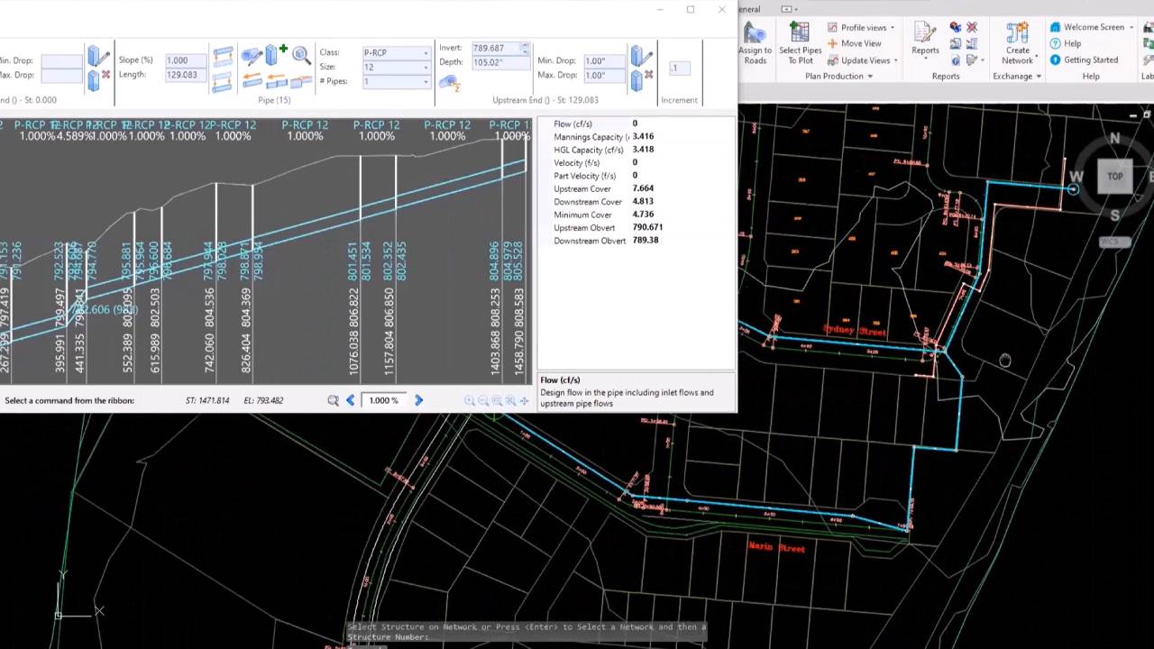
The Civil Site Design pipe designer stands out with its robust and interactive interface. One of its standout features is the visual representation of pipes in relation to the ground surface. This visualization ensures that designers have a comprehensive understanding of pipe depths, alignments, and positioning, fostering informed decision-making.
Moreover, the software is embedded with smart design algorithms. It doesn’t merely place pipes haphazardly. Instead, each pipe is meticulously designed based on critical parameters, such as minimum slope requirements and anticipated design flows. This ensures that the resulting network is not only functional but also efficient.
A unique feature of this module is its ability to display potential obstructions from other utilities. These obstructions are vividly color-coded based on their minimum clearances, offering designers a clear visual cue of potential conflict zones. Additionally, the software provides insights into incoming pipes, which play a pivotal role in determining manhole inverts, ensuring seamless integration and functionality.
In essence, Civil Site Design’s pipe design module is more than just a software tool; it’s a transformative solution that promises to redefine the standards of civil engineering and infrastructure planning. By melding user-friendly design with advanced technology, it sets the stage for a future where infrastructure design is both efficient and impeccable.


Civil Site Design Pipes includes all the tools you need to quickly create your pipe networks and avoid crossing services and other pipe networks.

Working inside the drawing environment, you can create and design Stormwater Drainage Networks, Sewer Networks and undertake general pipe design. Service obstruction checks are included in the design process for you to quickly optimise your designs and avoid conflicts between underground services.
Layout and create your pipe network by either clicking on screen or create directly from polylines or alignments. Whilst the initial pipe layout is based on minimum slopes and covers, the multiple Vertical Design Windows allow you to quickly adjust any pipe sizes and levels to achieve your desired outcomes.
From The Vertical Design Window interface you can see all crossing pipes and services, including clash detection. Edit pipes and pits by setting invert/obvert levels or move pipes up and down by increment. Insert in-line pipes wherever you require and review the pit drops and pipe levels.
Civil Site Design Pipes is synchronised with the Roads module, enabling both the pit levels and offsets to be directly connected to a road element and with dynamic updates as the road element is edited. All pipe networks can be displayed on the road Vertical Grading and Cross Section Windows to confirm locations relative to the road design.
The Reports Manager builds customised reports from any combination of attributes stored by the software and can be exported as comma separated files (CSV) for review in your preferred spread-sheet program or as an AutoCAD table in the drawing. Create pit and pipe schedules directly from your designs.
Using the Long Section plotting tools you can rapidly generate an industry standard output for your designs directly inside the AutoCAD drawing with control over the sheet layout and data included. Publish directly to AutoCAD as separate files or as layouts in the current drawing.
Sewer Pipe Design
Civil Site Design Pipes incorporates a comprehensive set of sewer pipe design tools.

Sewer house/property connections are included in the design tools and can check depth controls and minimum levels along the sewer network. Each house connection can be viewed in a Vertical Design window for editing and adjustment.
The sewer network will automatically adjust to ensure compliance with the minimum house connection levels, and you will be alerted if sewer pipe edits result in any compliance issues with house/property connections.
Interactive vertical design windows are able to display any branch of pipes in a network and complete with editing tools you can quickly and easily design a system to avoid all conflicts and service the house/property connection. All house connections, service obstructions and other networks display as crossing pipes, including clearance controls – as you make changes to pipe sizes and levels you can immediately identify and address any conflicts.
Detailed and specific reporting tools for sewer designers enable quick identification of any house/property connection issues.
Using the Long Section plotting tools you can rapidly generate industry standard outputs of your designs directly inside the AutoCAD drawing, including house connection controls and ready for immediate plotting. Publish directly to AutoCAD as separate files or as layouts in the current drawing.
Plan drafting occurs directly in the AutoCAD drawing including selected attributes from your design specific to sewer design.
Stormwater Design
Built specifically for the Australian stormwater drainage designer and applying the principles of the Australian Rainfall and Runoff manual and Rational Method design, Civil Site Design Pipes is a complete tool for designers wanting to create underground stormwater drainage systems.
Easily create drainage catchments directly from a Surface and polyline – catchment style libraries allow you to easily assign catchment criteria for common catchment types.
When a network is created the design flows are calculated and pipe sizes and levels are automatically assigned to manage the flows as well as minimum cover, slope and flow velocities.
As you make changes to pipe sizes and levels the Hydraulic Grade Line and all design information for each pipe automatically updates.
Using the Long Section plotting tools you can rapidly generate industry standard outputs of your designs directly inside the AutoCAD drawing, complete with HGL and other stormwater details and ready for immediate plotting. Publish directly to AutoCAD as separate files or as layouts in the current drawing.
